How To Draw Phasor Diagram For Rlc Circuit. Phasor diagrams are used in electrical engineering to represent the relationship of different ac signals at an instant of time. Web the impedance diagram for a typical series rlc circuit, inductive in nature, is shown in figure 5 and can be summarized as follows:
RC RLC RL Series Circuits your electrical guide from www.yourelectricalguide.com
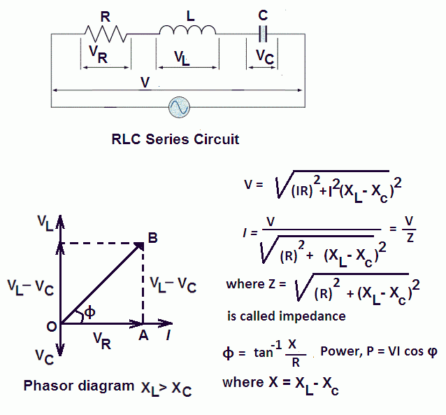
Web for the given circuit diagram calculate the rlc series circuit impedance, current, voltage across each component, and power factor. No more ratta maar 180k subscribers subscribe 15k views 1 year ago. Consider a circuit in which r, l, and c are connected in series with each other across ac supply as shown in fig.
The Ac Supply Is Given By, V = Vm Sin Wt.
Web for the given circuit diagram calculate the rlc series circuit impedance, current, voltage across each component, and power factor. Adjust the values of r, l, and c using the sliders. Web components of basic electrical circuit analysis of an rlc series circuit let’s consider the following rlc circuit using the current across the circuit as our reference phasor.
Web The Impedance Diagram For A Typical Series Rlc Circuit, Inductive In Nature, Is Shown In Figure 5 And Can Be Summarized As Follows:
1) phasor diagram of series rlc circuit. Change how the circuit is driven by. In case of series rl circuit, resistor and inductor are connected in series,.
Consider A Circuit In Which R, L, And C Are Connected In Series With Each Other Across Ac Supply As Shown In Fig.
No more ratta maar 180k subscribers subscribe 15k views 1 year ago. Phasor diagram of series rlc circuit topics discussed: 1) phasor diagram of parallel rlc circuit.
Web For Drawing The Phasor Diagram Of Series Rl Circuit;
Phasor diagram of parallel rlc circuit topics discussed: This simulation shows the phasor representation of a series rlc circuit. Hey delphi 33.5k subscribers subscribe 0 no views 1 minute ago how to draw phasor diagram of rlc series circuit?.
Phasor Diagrams Are Used In Electrical Engineering To Represent The Relationship Of Different Ac Signals At An Instant Of Time.
The total impedance (z) is equal to the. Web how to draw phasor diagram of rlc series circuit? Web 79k views 3 years ago network theory network theory: